The shape of the object is the main element of the geometry of the objects, but this is not the only one. By elements of the geometry of the objects we include all the specifications of the objects that you must define on the workspace (not available on Tooltabs or Object Inspector). The available elements may depend on the object types.
Nodes & Geometric Shape
Basically, the user must place a sequence of points (named nodes) on the workspace that defines the geometric shape of the object. A node is a significant point that is part of the shape. Consecutive nodes will be connected by straight lines or curves depending on the properties assigned to those nodes. The geometric shape is then constituted by straight or curve segments.
Read more about the geometric shape of the object including the nodes and the nodes properties in Classic Digitizing. |
|
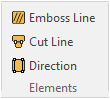
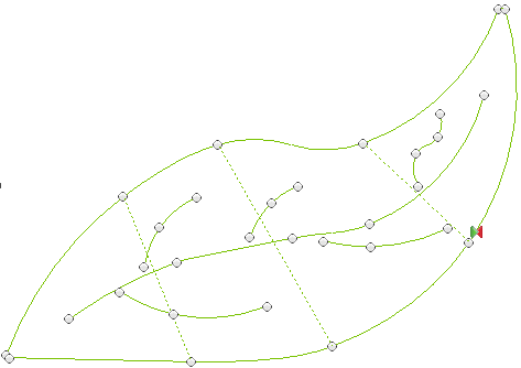
Direction Lines
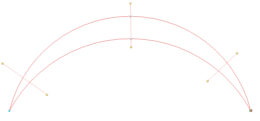
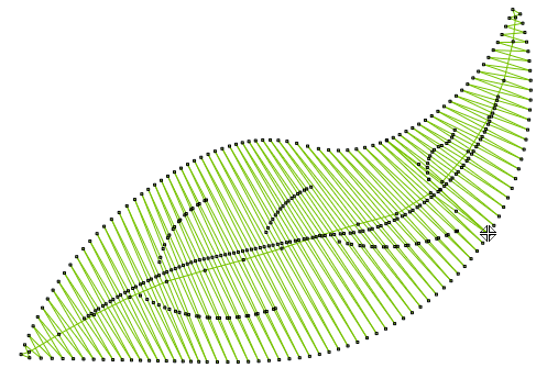
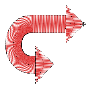
The direction lines specify the orientation of the stitches that fill the object.
It is represented by a line that has yellow square points on both ends.
|
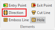
How to add a direction line? ➢Click on DIRECTION on the tooltab ➢Click on the workspace to place the first end of the direction line. ➢Click on the workspace to place the second end of the direction line. How to edit a direction line? ➢Click on any end of the direction line ➢You can move that end, delete the direction line, etc. |
If the object has only one direction line, the angle of that direction line will define the angle of most of the generated stitches. If the object has several direction lines, the angle of the generated stitches included between 2 direction lines will rotate between the angles of those direction lines. |
|
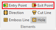
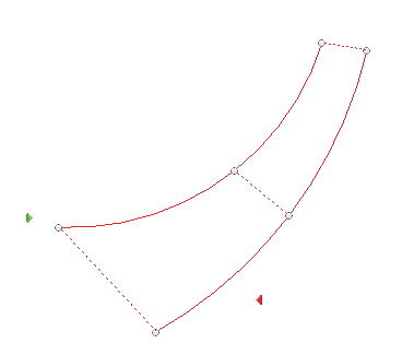
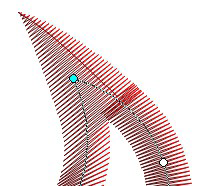
Entry and Exit points
The first stitch of an object is generated in the point of the object outline that is closer to the element called the Entry Point. The Entry point defines where the first stitch of an object is placed. On the other hand, the Exit point defines where the last stitch of an object is placed.
The Entry Point is represented with a green diamond. The Exit Point is represented with a red diamond.
|
How to define the entry / exit point? ➢Click on ENTRY POINT / EXIT POINT on the tooltab ➢Click on the workspace to place it. How to edit the entry / exit point? ➢Click on the entry / exit point ➢Move it (if the entry / exit points is placed over a node and it is not possible to move it, press and hold the Alt key while you move it) |
If the Entry and Exit points are not defined, such elements will be automatically defined by the application. The application will set those points on the nearest points of 2 consecutive objects (close point connection). |
|
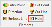
Holes
A hole is an empty area inside an Area object.
|
How to add a hole? ➢Click on HOLE on the tooltab ➢Insert the nodes of the hole. The last node must match the first node to close the hole. You can insert as many holes as you want. |
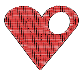
According to the stitch fill styles, the hole may offers 3 different results. You can select the hole properties on the Object Inspector.
•No Fill The area of the hole is empty (free of stitches) |
|
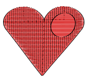
•Zig Zag Fill The area of the hole is filled with stitches, but no stitches ends are located inside the area of the hole (the stitch ends are located in the border of the hole). |
|
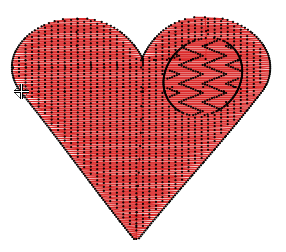
•Pattern Fill The area of the hole is filled with stitches, and the stitches that are inside the area of the hole are placed according to a pattern fill style. |
|
Emboss Line
You can define a path (the emboss line) within the object outline (path with straight/curve/corner nodes). When any stitch of the main fill crosses that path, that stitch is divided (split) on that cross point. When several stitches of the main fill are divided by the emboss line, the consecutive needle penetration along the emboss line will produce an emboss effect. Emboss effects makes sense for zig-zag and pattern stitches (it makes no sense for programmable stitches, etc).
|
How to add an embossed line? ➢Click on EMBOSS LINE on the tooltab ➢Insert the path (sequence of nodes with their properties) inside the object. |
You can add several emboss lines to this object type. |
|
Cut Line
You can split an area object in 2 or more sub-objects.
Except for auto-fill, all sub-objects included in the object have the same stitch fill properties, but some elements of the geometry of the objects change. The shape of the sub-object is defined by the area object outline, the holes (if any) and the cut lines. You can define different direction lines for each sub-object. This element is recommended when you have to convert a single complex area (which only support 1 direction line) into several simple areas to use turning stitch direction lines.
The auto-fill style automatically adds Cut Lines to split an area object into sub-object, which may have different stitch fill styles according to the sub-object shape.
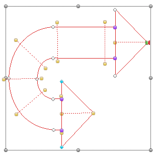
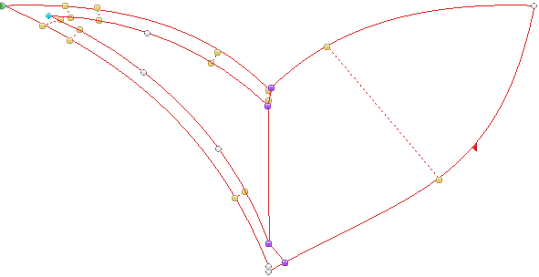
The Cut Line is represented by a line that has violet square points on both ends.
|
How to add a cut line? ➢Click on CUT LINE on the tooltab ➢Click on any point of the outline of an area object, or the hole. ➢Click on a second point of the outline of the area object, or the hole. You can add several cut lines to this object type. |
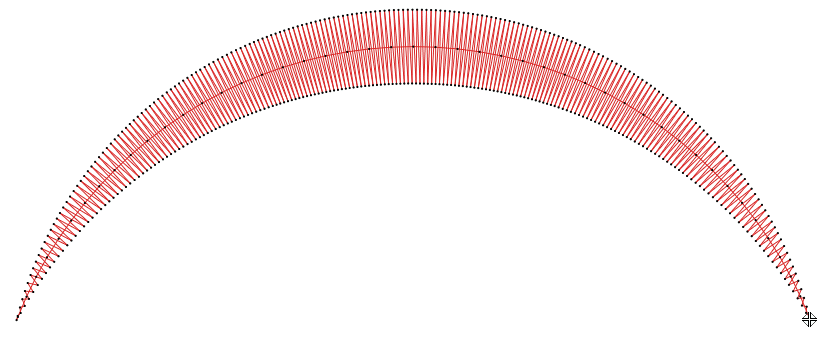
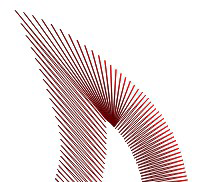
Several cut lines on a Turning Area with Zig-Zag Stitches. |
|
|
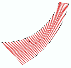
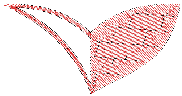
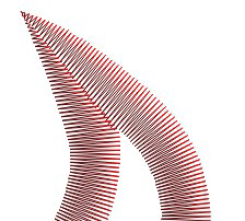
Several cut lines on an Area with Auto-Fill. |
|
|
Cut Line and Direction
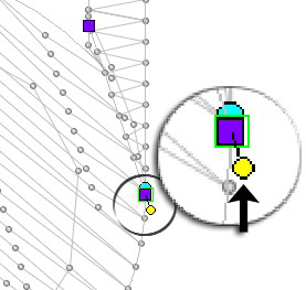
You can also use the same Cut Line to set the angle of the stitches (as if it is a Direction Line).
|
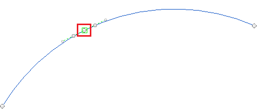
How to set the Direction on the Cut Line? ➢Click on one of the Cut Line ends (violet) to edit it. A yellow circle is displayed linked to the cut line end. ➢Click on it to modify modify this cut line attribute (turning it into a direction line)
If you want to set a cut line as a direction line too, press and hold the Shift key before creating the cut line. |
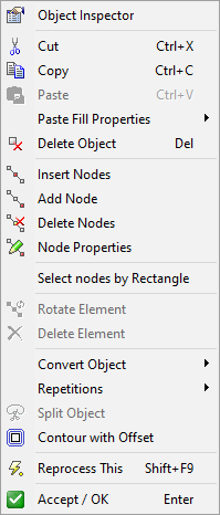
Other node properties
There are extra node properties that can be accessed from the context menu. To open the context menu, first select a section. Then, select a node and right click on it. If you have selected only one node, the selection tool will only be applied to that node. However, you may also apply a tool to a the group of nodes.
|
Insert nodes: Insert a node between the one selected and the previous one. The new node is located halfway between them and has the same features of the selected one. This tool is available when you have selected only one node. Add nodes: Add several nodes to a reference. The added nodes will appear after the selected node and are placed manually by the mouse cursor. Delete nodes: Delete the selected nodes from the reference. You can also delete node pressing the DELETE key. You can apply this tool to a group of nodes as well. Rotate nodes: Rotate the figure from the selected node. After selecting this tool, place the mouse cursor over the node, click and rotate the object. Corners: There are have three corner modes available.
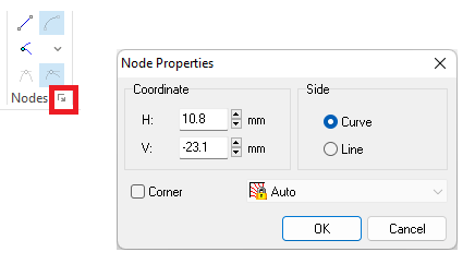
Open and Close: These tools allow to modify the selected section, opening or closing a path object. Node Properties: Opens the "Node Properties" dialog box. You can define the node exact coordinates, set it straight or curved; and select the corner mode. Note: If several nodes are selected, several functions may not be available. |
|
You can also edit the node properties using the small button at the right of the Nodes group at the tool tab |