Classic Digitizing (or Manual Digitizing) is the most important digitizing mode. While other digitizing modes can be missing, this one is essential to create any design. Any object geometry can be created through this digitizing method as the user can define and control the geometric shape and other geometric elements in detail.
Basically, the user must place a sequence of points (named nodes) on the workspace that defines the geometric shape of the object. A node is a significant point that is part of the shape. Consecutive nodes will be connected by straight lines or curves depending on the properties assigned to those nodes. The geometric shape is then constituted by straight or curve segments.
Arc & Bezier Curves
This application supports 2 different methods to create shapes with curves (curve types):
ARC Curve |
The connection (segment) between nodes is automatically created with 2 perfectly spliced arcs (portions of circles). The arcs depend on the nodes positions, nodes properties and also adjacent segments. No other specification is required. |
BEZIER Curve |
The connection (segment) between nodes is made of a Bezier curve. The shape of this curve depends on the nodes positions and the Bezier control points. While digitizing each node, the user must specify additional Bezier control points (dragging from the node) to define the curve. |
Objects can be created using any curve type. You don't need to use both curve methods. You can choose any of them according to your convenience. Probably the ARC curve is easier to learn and faster to use (it usually offers more predictable results), then if you are not used to other graphic applications you may prefer to use ARC curves. Instead, if you are familiar with other vector graphic applications or if you will create designs from vector images, BEZIER curve is your best choice.
|
Both curve types can offer you the same result. The main difference is the way you create the shapes with each method. |
|
You can modify the default curve type used by the application from the System Settings (tooltab FILE > Options > System Settings > Create & Edit > General > modify the CURVE TYPE. |
How to create the geometry of the objects using manual digitizing?
As mentioned, the nodes are a sequence of points of the geometry with properties (connection properties) that define the line/curve segment between consecutive nodes. Nodes may have the following properties:
|
Line/Curve |
Property produces |
Representation |
|---|---|---|---|
|
Straight Line |
The last segment is a straight line |
A small square |
|
Curve |
The last segment is an arc/bezier curve |
A small circle |
|
Normal/Corner |
Property produces |
Representation |
|---|---|---|---|
|
Normal |
The node does not change the continuity between 2 curves |
The white fill |
|
Corner |
The node changes the continuity between 2 adjacent curves |
The cyan fill |
These are some examples of open path objects created in the indicated sequence, where the node properties have different marks to recognize them.
|
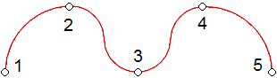
The node 2 (curve-normal) defines the segment 1-2: curve The node 3 (curve-normal) defines the segment 2-3: curve The node 4 (curve-normal) defines the segment 3-4: curve The node 5 (curve-normal) defines the segment 4-5: curve Note that, as the nodes are not corners (they are normal), there is a continuity (same angle) on the curve between 2 adjacent curve segments.
|
|
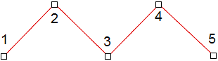
The node 2 (line-normal) defines the segment 1-2: line The node 3 (line-normal) defines the segment 2-3: line The node 4 (line-normal) defines the segment 3-4: line The node 5 (line-normal) defines the segment 4-5: line
|
|
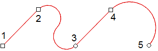
The node 2 (line-normal) defines the segment 1-2: line The node 3 (curve-normal) defines the segment 2-3: curve The node 4 (line-normal) defines the segment 3-4: line The node 5 (curve-normal) defines the segment 4-5: curve Note that, as the nodes are not corners (they are normal), there is a continuity (same angle) on the curve between 2 adjacent curve segments.
|
|
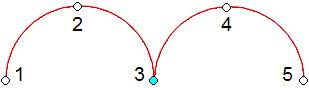
The node 2 (curve-normal) defines the segment 1-2: curve The node 3 (curve-corner) defines the segment 2-3: curve The node 4 (curve-normal) defines the segment 3-4: curve The node 5 (curve-normal) defines the segment 4-5: curve Note that, as the node 3 is a corners, there is a discontinuity (different angles) between the adjacent curve segments 2-3 and 3-4.
|
How to insert nodes (points and properties)?
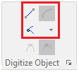
While digitizing in the classic mode, there are some tools in the tooltab to set the nodes properties.
|
The functions LINE and CURVE of the first row define the line/curve property of the following nodes to insert. If the function LINE is activated, the following nodes you are inserting will be of this kind. Analogously, if CURVE is activated the following inserted nodes will be curve. The second row defines the normal/corner property of the following nodes to insert. If the function CORNER is activated, the following nodes you are inserting will be corners, but the "normal" value is assigned when the CORNER function is nor activated, Then, one of the ways to set the properties of the nodes (line/curve, normal/corner) is to set them on the toolbar before inserting the corresponding node on the workspace. Certainly this way is not very productive to insert the nodes as it requires to move the mouse cursor from the working place to the tooltab very frequently, but there is a second way to insert the nodes more efficient. The second way to set the properties of the nodes (line/curve, normal/corner) is to define default values (they are the values you see in the tooltab) and switch the value with a keyboard combination. This way does not require to move the mouse cursor to any other place than the nodes positions. Probably the default values CURVE + NORMAL are the best choice. |
See both ways applied to the previous example. On the first way (not recommended) we will change the properties from the tooltab when required. On the second way (recommended) we will keep the default values (we won't change the tooltab values).
You may be comfortable with the following default values:
|
Curve Segment |
Switch to straight line using the Shift key
|
|
Normal (curve continuity) |
Switch to corner line using the Control key
|
|
|
1 |
|
|
1 SH |
|
|
1 SH |
|
|
1 |
Using Right Click - Left Click mode
Instead of using the Shift key to switch between curve and straight nodes, you can use the right mouse button to enter straight nodes and left mouse button to enter curve nodes.
|
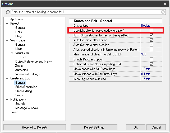
Instead of using the Shift key to switch between curve and straight nodes, you can use the right mouse button to enter straight nodes and left mouse button to enter curve nodes. Activate this mode from the HOME tooltab > System group > Settings. In the tree at the left select Create and Edit - General and check "Use rigjt click for straight nodes (creation)" Consider that: •This mode applies only during creation •When this mode is active, use the SPACE BAR key to open the context menu •You can still use the Ctrl key to enter corner nodes
|
|
1
|
|
Important: After you enter any node, the software draws an "elastic" segment from the node you have just entered to the current mouse pointer position. This "elastic" segment is drawn as straight or curve depending on the current setting (straight / curve) in the Nodes group at the Tool tab. However, this setting applies only to the "elastic" preview because, no matter the setting, the next node will be straight if you press the right mouse button or curve if you press the left mouse button. We suggest to use as default a straight setting in the Nodes group. With this, all "elastic" preview segments will be straight. If you are going to enter a curve node (left click) you can press the SHIFT key to get an "elastic" curved preview before placing the node. This way you will have a better preview of the contour before placing the curved node (left click) |
How to edit the nodes of an object (arc curve)?
After an object is created you can fully edit it, including the position and the property of each node. Then, you can insert the nodes quickly during the objects creation process and then you can easily edit any point to adjust the position and the node properties.
➢Click on EDIT OBJECT to activate the object editing mode
➢Select (click on) the object to edit
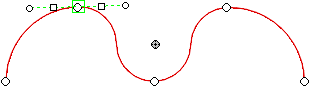
➢Select (click on) the node (of that object) to edit
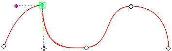
|
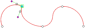
The node has been selected (highlighted) New marks linked to that node are displayed: they are the angle handles. Those handles are symmetric (both sides have the same length) and aligned (the angle is the same on both sides). When the nodes is selected, the properties of the nodes are displayed on the toolbar. You can change the properties from that place. |
|
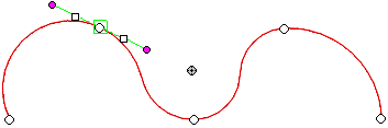
Plus... You can also change the angle of the node as if you were working with bezier curves, through the handles. ➢Move the angle handle (circle) to change the angle of the node from the "natural angle value for arc curves" to the angle you want. The handls will become magenta, that color refers to a user defined angle. ➢If you prefer to return the angle to its natural value, just click on any small square to release the user defined angle. |
|
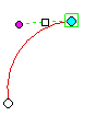
Plus... You can also change each of the angles of the nodes separately as if you were working with bezier curves, through the handles. ➢Press and hold the Ctrl key and move the angle handle (circle) to change the angle of that node (independently from the other angle of the node) to the angle you want. The node will become cyan as it will loose the continuity of the curve segments at each side of the node. ➢If you prefer to return the angle to its natural value, just click on any small square to release the user defined angle. |
How to insert nodes using BEZIER curves?
Bezier curves require to specify the position of the node and the angle of the curve segment on the node point. Unlike arc curves where the angles of the curves at the nodes is automatically calculated according to the node points and their properties, the angle on bezier curves doesn't depend on other nodes, it is just defined (as a property) when the node is created.
|
To define both node position and the curve segment angle: ➢Press and hold the mouse left button on the place of the workspace where you want a node, and drag the cursor in the direction of the exit angle you want for that node. The angle between the mouse cursor and the node will define the angle of the curve segment on the node, and the distance between the mouse cursor and the node will define the amplitude of the curvature. ➢Release the mouse left button and repeat these steps for the following nodes. You may find information about how to digitize with bezier curves on internet. |
How to edit the nodes of an object (bezier curve)?
After an object is created you can fully edit it, including the position and the property of each node. Then, you can insert the nodes quickly during the objects creation process and then you can easily edit any point to adjust the position and the node properties.
➢Click on EDIT OBJECT to activate the object editing mode
➢Select (click on) the object to edit
➢Select (click on) the node (of that object) to edit
|
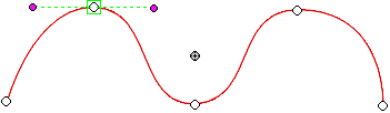
The node has been selected (highlighted). The marks linked to the node are the bezier handles. You can also change the angle of the node through the handles. In this example the handles are:
|
|
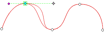
If the node is not symmetric
➢You can move the bezier handle to change the amplitude of one of the sides only, and the result is a change of the curvature of that curve segment. |
|
If the node is corner
You can also change each of the angles of the nodes separately through the bezier handles. ➢Press and hold the Ctrl key and move the angle handle (circle) to change the angle of that node (independently from the other angle of the node) to the angle you want. The node will become cyan as it will loose the continuity of the curve segments at each side of the node. This way will automatically change the property to corner. Then you won't need to press the Ctl key to move the angle again. |
How to create embroidery objects using manual digitizing?
In this article we have already explained how to insert the required nodes to define the geometry of the object. Now we will describe different some kind of objects and explain how to create them.
As this article is focused in the classic digitizing mode, it doesn't include all the available object types or the details of each object type. You will find the complete information about object types and fill styles in the following articles.
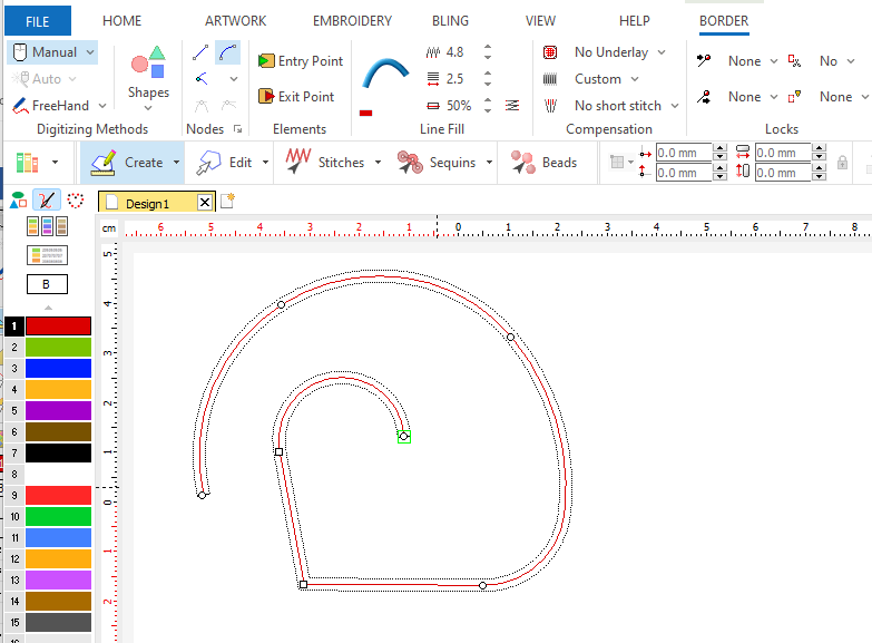
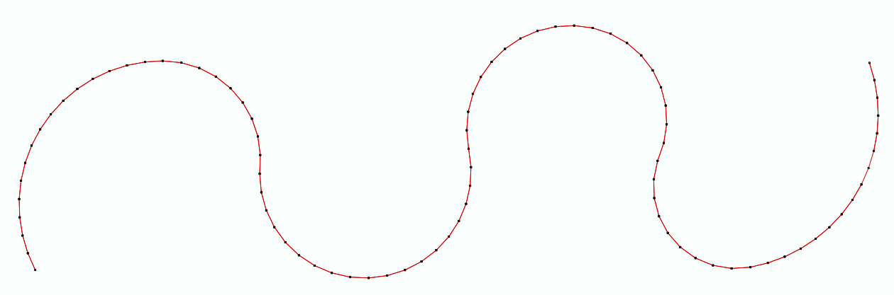
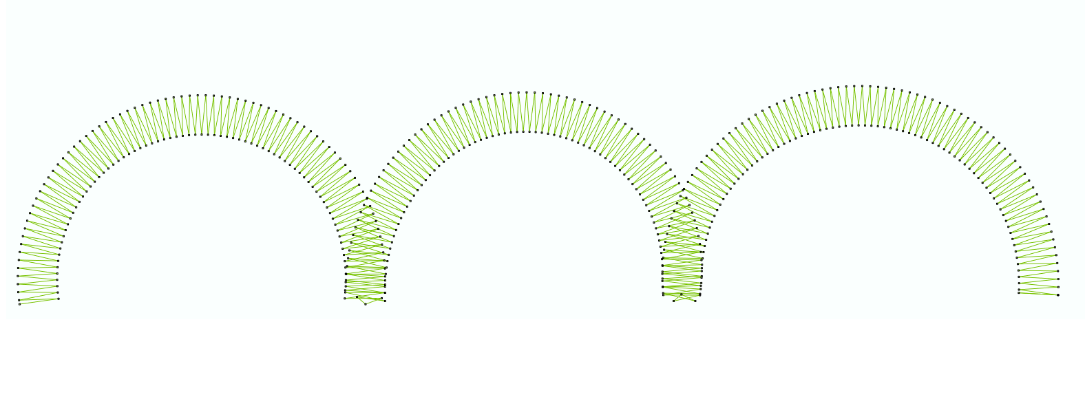
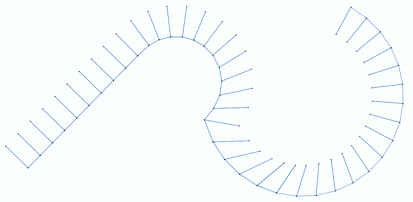
➢Click on CREATE OBJECT, on the MAIN bar and select the PATH Embroidery Object + ZIGZAG STITCHES fill style. You can select the object type from the tooltab EMBROIDERY or through the drop-down menu on the CREATE OBJECT arrow. ➢Click on MANUAL digitizing, if required (this is the default digitizing mode). ➢Create any open path on the workspace with straight lines and curves as explained previously. ➢Click on the Enter Key to confirm the shape and generate the stitches. ➢Click on EDIT OBJECT to modify the nodes positions or any node property. ➢Click on the Enter Key to confirm the shape and generate the stitches. |
|
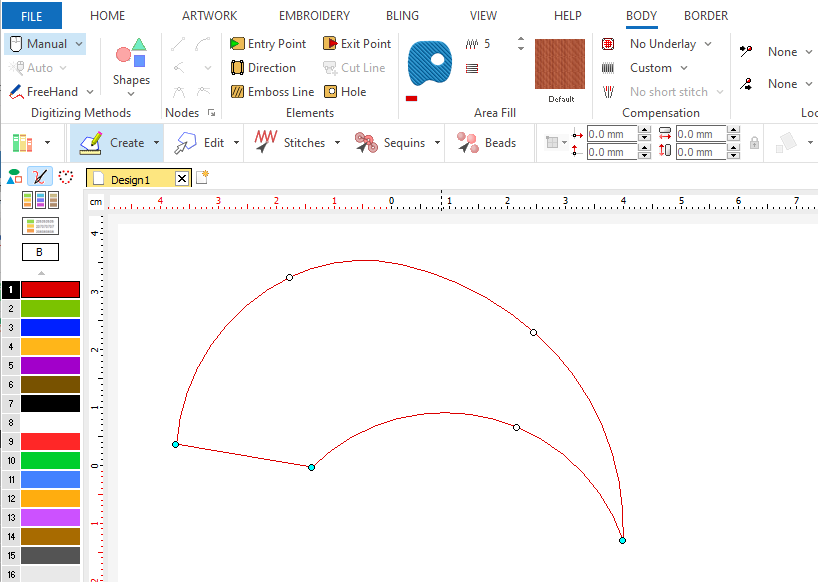
➢Click on CREATE OBJECT, on the MAIN bar and select the AREA Embroidery Object + PATTERN STITCHES fill style. You can select the object type from the tooltab EMBROIDERY or through the drop-down menu on the CREATE OBJECT arrow. ➢Click on MANUAL digitizing, if required (this is the default digitizing mode). ➢Create any close shape on the workspace with straight lines and curves as explained previously. ➢To close the shape, click on the first node. ➢Click on the Enter Key to confirm the shape and generate the stitches. ➢Click on EDIT OBJECT to modify the nodes positions or any node property. ➢Click on the Enter Key to confirm the shape and generate the stitches. |
|
Additional tools available during manual digitizing
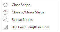
While entering the nodes during manual digitizing, there are some useful tools available at the context menu (right click). Note that not all the tools are available for all type of objects.
|
•Close Shape: Closes the contour by joining the last node entered with the first node. |
•Close w/Mirror Shape: Closes the contour by mirroring the node sequence already created. |
|
•Repeats, the indicated number of times, the whole sequence of nodes already created, inserting it starting from the last node entered. (*) |
|
•Moves the last entered node at the specified distance from the previous one |
(*) Feature available starting from version 23.20
Details about Object Types are available in Object Types