What is an Area object?
|
An area is an object type made of a continuous sequence of nodes that define the geometry of the object, where the last node matches with the first one (a closed shape). The shape defined by the nodes is the outline of the area object. The properties of the nodes define if the segments between the nodes are straight lines or curves, and if the node shows a continuity or a discontinuity (also known as corner) of the curves (*). The main requirement for area object is that: No part of the object's outline should cross another part of the same outline, as it me produce unpredictable results (that is not an area).
There are 3 sub-types of areas according to the kind of "direction lines":
|


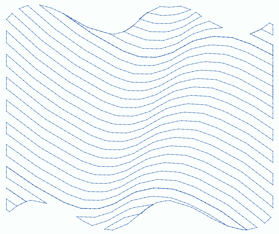
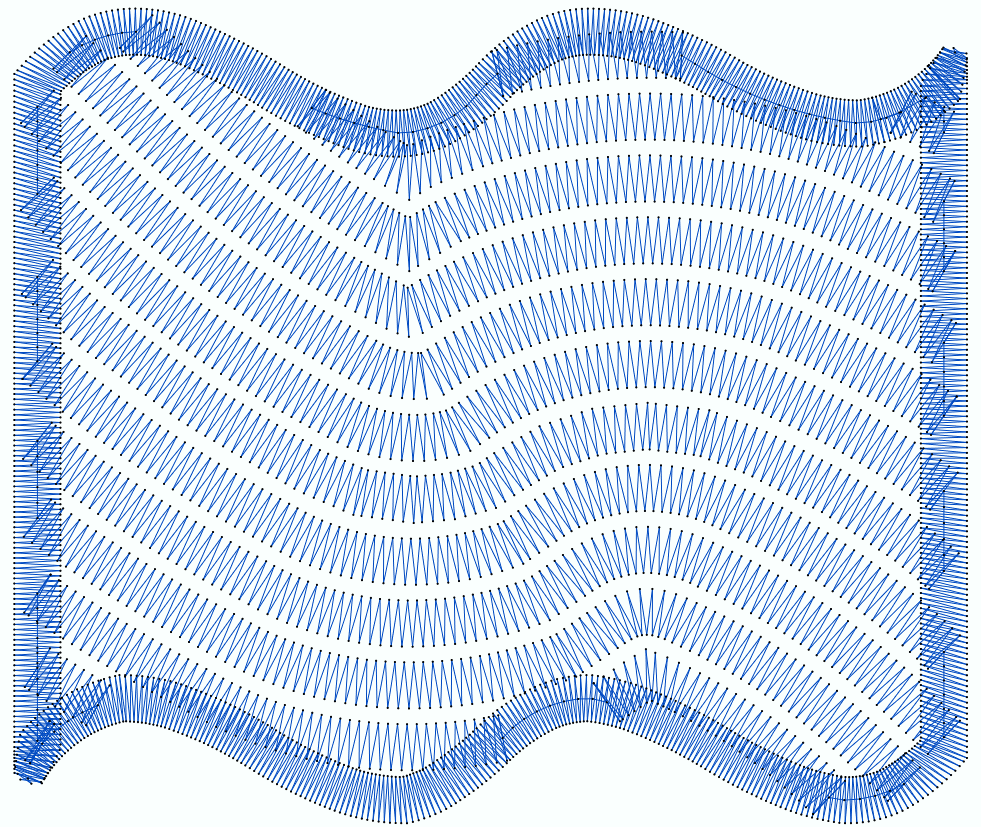
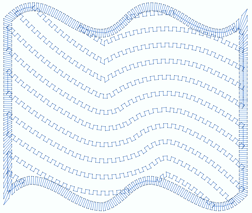
Samples of Flexible Area Objects with several Stitch Fill styles.
|
|
|
Elements of the Flexible Area Object
|
•Sequence of nodes of the outline (1-7) ** •Sequence of nodes of the hole 1 (8-10) •Direction path (11-13) ** •Entry point (14) •Exit point (15)
** required element |
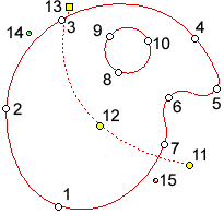
OUTLINE NODES |
They are points of the main geometry of the object (outline), which include properties to define the segment (line or curve) between 2 consecutive nodes.
|
HOLE NODES |
They are points of the holes of the object, which include properties to define the segment (line or curve) between 2 consecutive nodes. The uniform area object may have 1 or more holes, or none.
|
DIRECTION PATH |
This is a path with nodes (line or curve) that represent the stitch direction of the main fill style. If the direction line is not specified, the application will define it as an horizontal line.
|
ENTRY POINT & EXIT POINT |
The entry point is the point of the object where the first stitch is placed. The exit point is the point of the object where the last stitch is placed. The connection between the exit point of an object and the entry point of the following object may vary according to the distance between them. If both points match there is no need to add anything to join them. Instead when there is a distance between them, the connection is a jump-stitch with or without a thread trim. You can set the entry point and the exit point wherever you want. It is usually convenient to define the entry point of an object close to the exit point of the precedent object in order to avoid long jump-stitches and frequent thread trims. We suggest you to plan the sequence of object of the design previously to minimize the distance between exit and entry points of consecutive objects. The software includes a "close point connection" feature for the case you prefer not to set each entry and exit point. This feature automatically moves the entry and exist points of the objects while they are created or edited to reach the minimum distance between them on-the-fly. You can move the position of the entry or exit points at any time (object editing). You can also set the "close point connection" mode. The true entry/exit points are the points of the shape that are closer to the user defined entry/exit points.
|
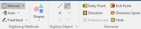
How to create a Flexible Area Object?
➢Click on CREATE OBJECT, on the MAIN bar and select the FLEXIBLE AREA Embroidery Object + RUNNING STITCHES fill style (or any other stitch fill style). You can select the object type from the tooltab EMBROIDERY or through the drop-down menu on the CREATE OBJECT arrow. ➢Click on MANUAL digitizing. ➢Insert the OUTLINE NODES in the workspace (read about node properties to create straight or curve line segments). ➢Click on HOLES if you want to add one or more holes on the object. ➢Insert the HOLE NODES in the workspace (read about node properties to create straight or curve line segments). ➢Repeat this step if more holes are required. ➢Click on DIRECTION to define a custom direction line. ➢Insert the nodes of the direction path (read about node properties to create straight or curve line segments). ➢Click on ENTRY POINT if you want to set the entry point, otherwise let the application optimize it. ➢Define the entry point with a click on the position of the workspace where you want the first stitch of this object, or let the application optimize it. ➢Click on EXIT POINT if you want to set the exit point, otherwise let the application optimize it. ➢Define the exit point with a click on the position of the workspace where you want the last stitch of this object. ➢Click on ENTER or click on Accept/OK from the context menu to confirm the object. |
|
Available Stitch Fill Styles for Flexible Area Object |
|---|
Advanced Fill Styles for Flexible Area Object |
|---|
•Flexible Area + Macro Running Stitches •Flexible Area + Macro Zig-Zag Stitches |
Specialty Fill Styles for Flexible Area Object |
|---|